ArmCAD
About
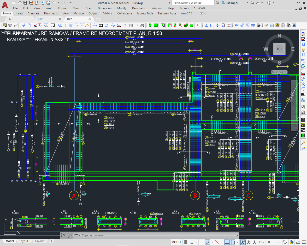
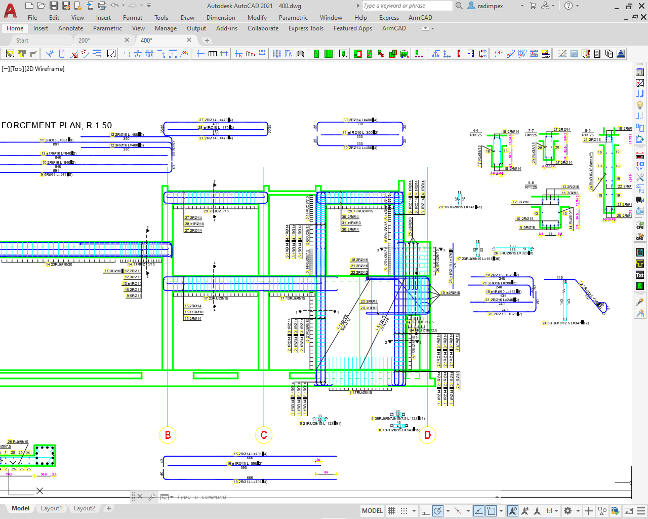
ArmCAD reinforced concrete detailing program
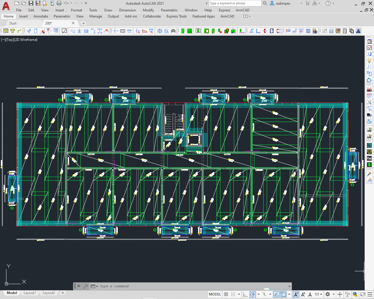
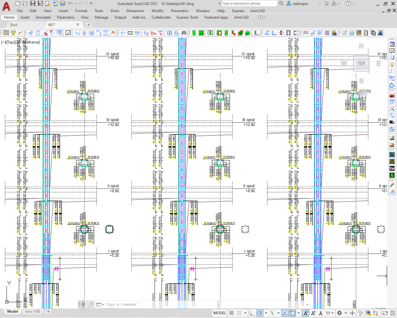
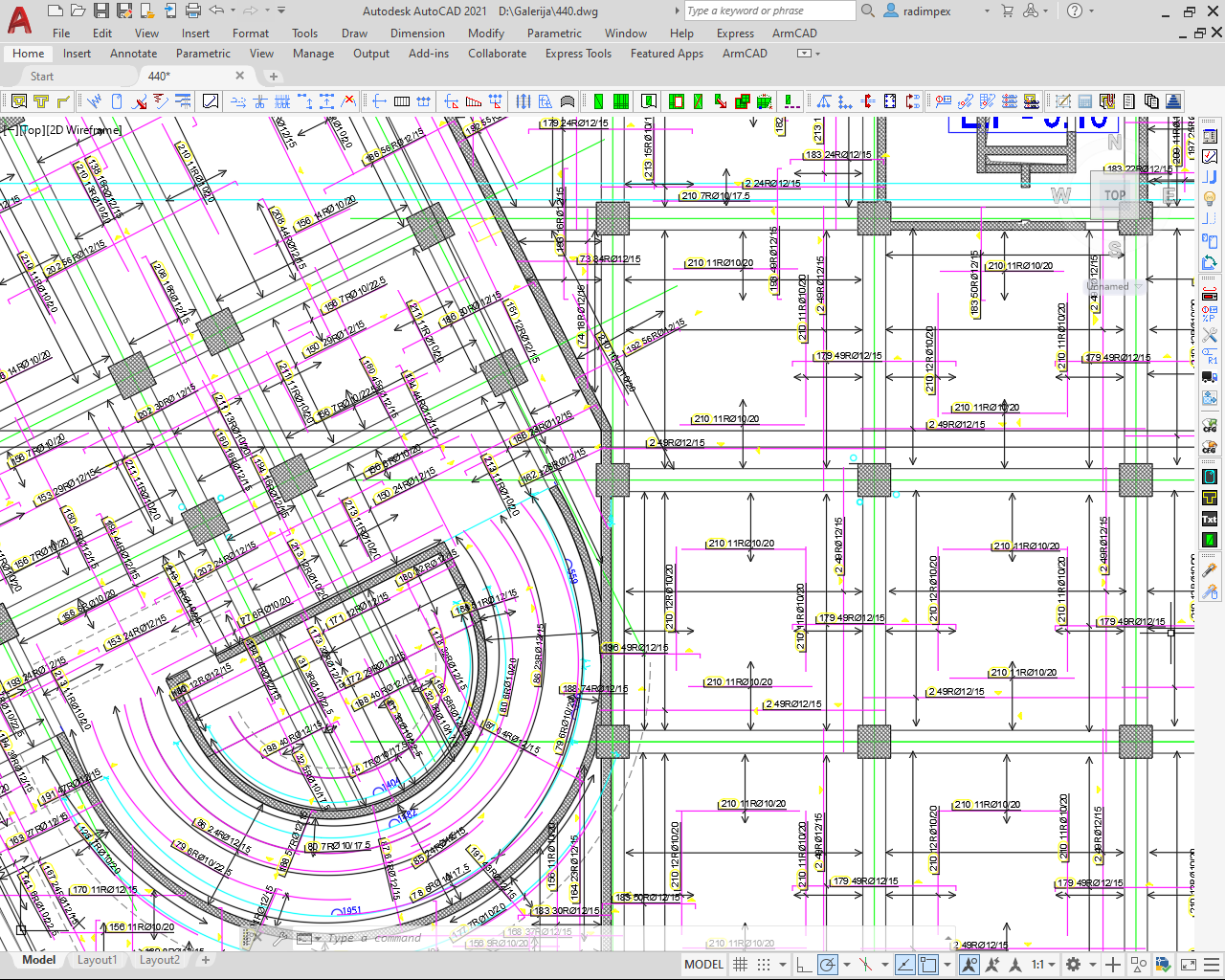
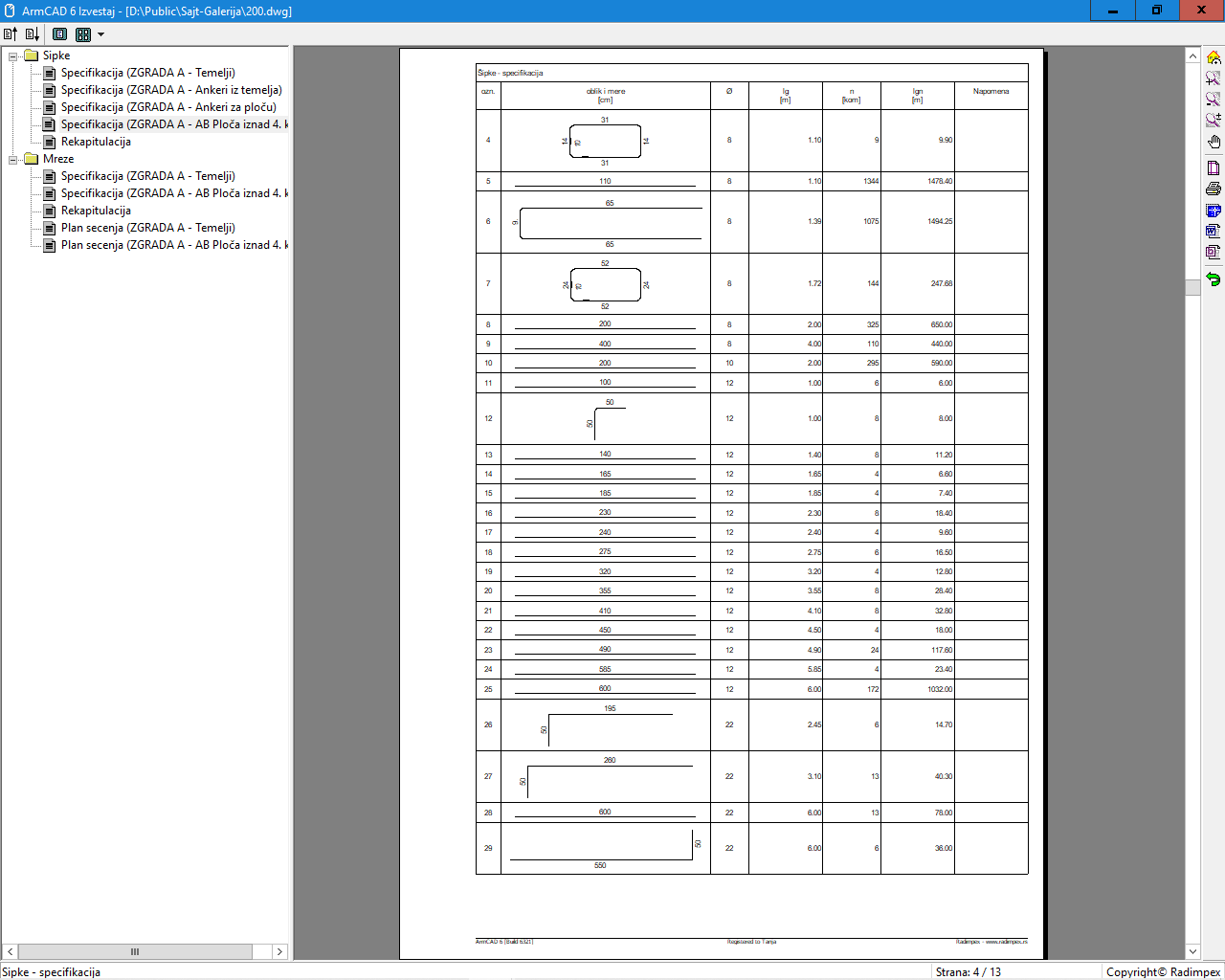
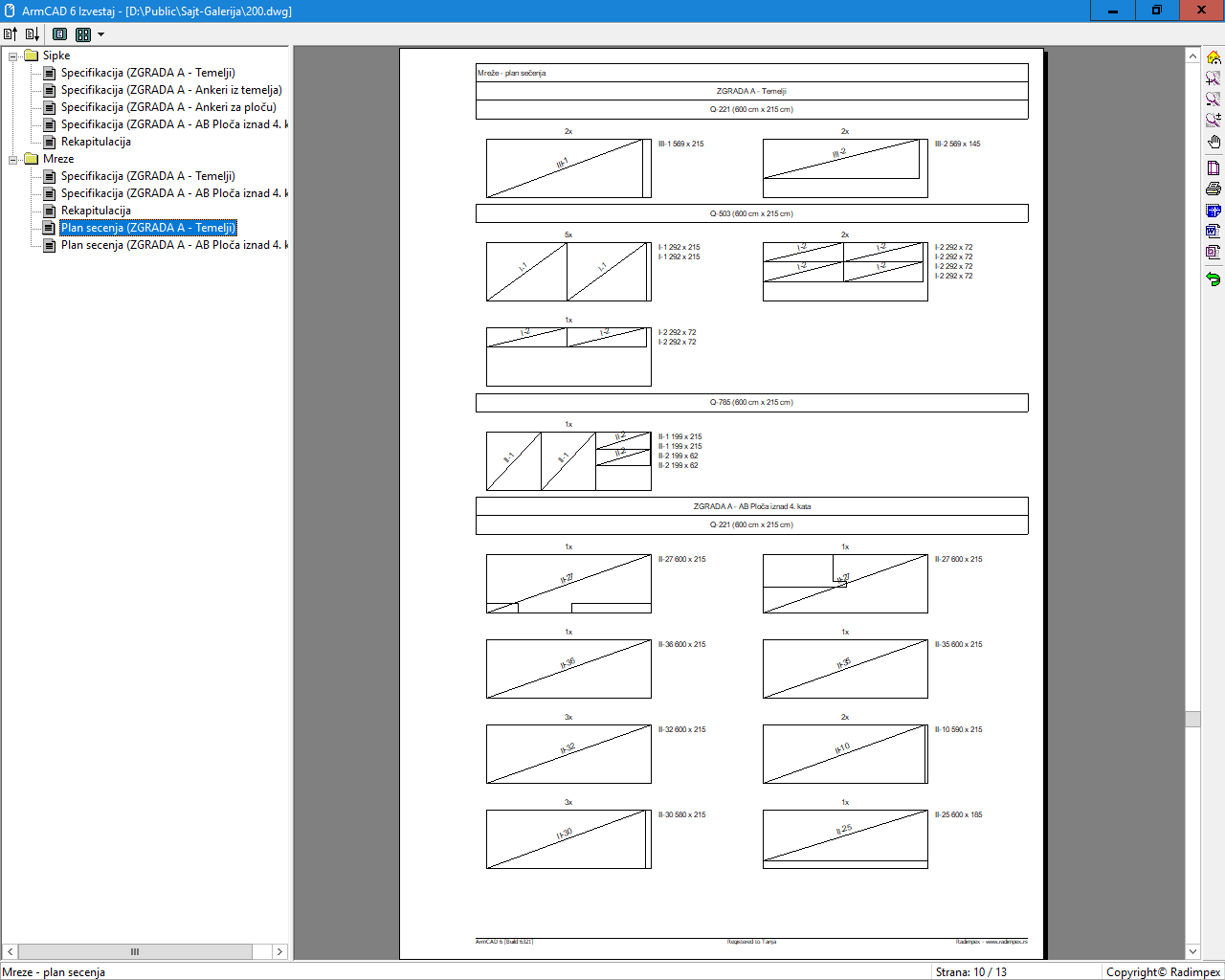
ARMCAD is a program, which integrated into AutoCAD or BricsCAD, helps to create high quality professional drawings of reinforcement details. ArmCAD frees the user from the hardest part of the job - sorting, positioning, marking, counting, formatting, anchoring and error control. All this is enabled with automatic updating of all subsequent changes. At any time, the program enables the automatic generation of a reinforcement specification that accurately and precisely displays the geometry and quantity of each of the bar positions used in the drawing. Along with the specification, a recapitulation of the reinforcement is automatically generated, which is a summary of the quantities of reinforcement. When using mesh reinforcement, in addition to the specification and recapitulation, an optimized cutting plan is automatically generated, which allows the amount of cut and unused parts of the mesh to be as small as possible.
ARMCAD 7 was created as a result of our many years of work on further development of ARMCAD 6 program, and presents its comprehensive improvement and enables a faster, easier and more accurate process of drawing reinforcement details. Many of the novelties in the ARMCAD 7 program stem from the practical and functional requirements of users, whose contribution to the development of the ARMCAD program is immeasurable.
Program's main functions
• drawing, positioning, dimensioning, marking and editing of bars, series of bars and mesh reinforcement
• Automatic creation of complete and detailed reports of specification, recapitulation and cutting plan of bars and nets
• Supports the use of bars of limited, predefined length and allows automated beaking and continuation of bars.
• Fully adaptable to different standards and styles.
• Enables automatically generated ready-made drawings based on the concrete design calculation performed by program Tower (versions 5, 6, 7 and 8).
• Fully integrated into AutoCAD or BricsCAD programs. Supports AutoCAD 2010 and newer. Supports BricsCAD v14 and newer.
Overview of new features in ArmCAD 7
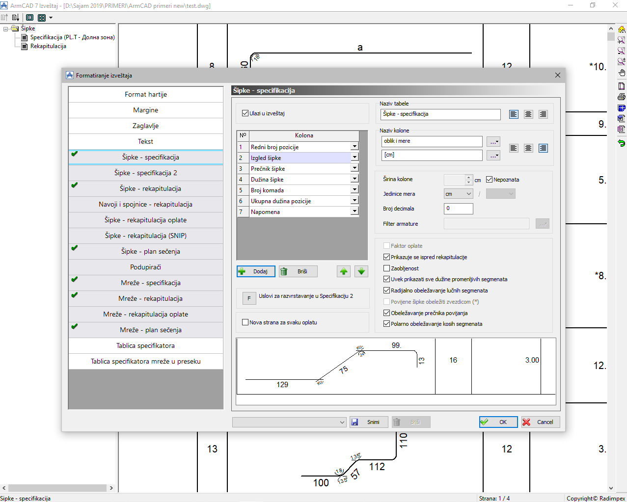
New features in report
In this group, the most important new features include the ability to display the bending diameter, adjust the font width factor, display oblique segments of the bar with deflection angles, adjust the orientation of the bar in the display in the specification, additional reports, additional columns and new ways to separate and group data, support for British standard specification - via Shape Codes that are determined automatically, etc.
New features in entity layout
Among the most important new features in entity layout are support for the technology of mechanical reinforcement coupling (threaded couplings), including labeling and specification and recapitulation of fasteners, the ability to adjust the appearance of the labeling for each entity separately, new ways of displaying bars, series, labels, new ways for their adjustment, displaying the markings of the installation layer of the bar or series, displaying the orientation of the mesh in cross section, new types of display of structural reinforcement, etc.
New features in labeling, positioning and referencing
The most important innovations in these areas are the newly introduced uniform specifiers and the possibility of their automatic generation (uniform in terms of the dimensions of the boxes in which they are placed), labels with center alignment, the ability to skip bars during crossing, the option of labeling additional markings to the bar position, additional new types of sorting and numbering positions, the option of creating specifiers for grids in the cross-section, etc.
New features in defining and editing geometry
The most important new features in defining and editing geometry are the use of standard mesh geometry in cross-section, the ability to add segments to the network in cross-section, support for arcs in standard bar geometries, etc.
New features in reinforcement continuing and anchoring
Among the most important new features are the function of automatic continuation (break) of series of bars with alternating position of overlap, continuation in series of bars with arc geometry, continuation of circular bars (division into arc bars of transport length), anchoring (extension) of mesh reinforcement, etc.
New features in the user interface
In this group of new features, the most important are the ability to group labeling styles, control of ARMCAD’s auto-start when opening drawings with ARMCAD entities, several additional visibility filters, quick position selection and payments in dialogues via drawing, compliance control of weights and dimensions of networks between drawings and data in a database of type grids, the direct orbit of the bar geometry in dialogues, improving the import of reinforcement from the Tower, etc.
New features in quantity calculation and cost optimization
The most important changes are the possibility of using the remaining cut parts of the net within the same payments with the possibility of determining the most optimal order of installation of mesh positions, the possibility of entering the correction of bent bar length in relation to bar diameter and bending diameter, etc.
The key features of ArmCAD 6
Support for another CAD platform
In addition to Autodesk's AutoCAD program, ArmCAD 6 also has a release for Bricsys' BricsCAD program. BricsCAD is a DWG compatible and very affordable CAD platform. ArmCAD 6 editions for AutoCAD and BricsCAD are exactly the same in terms of functionality.
Optimal use and savings of standard reinforcement
ArmCAD 6 includes complete support for using bars of pre-defined lengths (purchase or transport length). Added the ability to automatically split and continue bars and series of bars (constant and variable) in several predefined ways. Positions with bars whose lengths exceed the purchase length is specially marked, and we especially pay attention to the automatic creation of the optimal plan for cutting the bars so that the amount of waste is the smallest.
Optimal use and saving of mesh reinforcement
ArmCAD 6 brings a new functionality - paving with series of networks in phase construction mode. In this way, a piece of net left over from the previous construction phases can be used in paving the current and subsequent phases leading to significant reinforcement savings. The possibility of creating a cutting plan with an exact fit has been introduced in order to save even more.
Improvements in drawing and marking
New types of pointers have been introduced - the so-called "counter" pointers as well as marking the pointers with a "mini" position marker. Additional adjustment is enabled by introducing additional parameters - e.g. adjust the spacing in the elevation printout or adjust the color of the arrow pointer. It is also possible to specify a separate color for each entity that overrides the standard color of that entity. A special, "extra-rare" batch display has been added, in which the user can manually or semi-automatically specify which batch bars are drawn and which are not, but also a special batch display mode basically with the first and last bars displayed. In addition, a "full view" is provided, which makes up the true geometry of the bars in the down position. To make it easier to work with Layouts and the different sizes in them, it is possible to influence the size of each elevation individually. Changes in the positions of the grip points resulted in easier handling and better setting of the angle of the specifier, cross section and cross section mark.
Improvements in assigning bars
It is possible to easily insert new bar segments at the beginning or end, convert "ordinary" stirrups into "seismic" (with folded segment) and vice versa, and for special bars a special type of special with 3D geometry was introduced to facilitate the definition of so-called "riders". It is possible to directly instantiate the representative (instead of the real instance of the bar) when creating a new position.
Improvements in assigning a series of bars
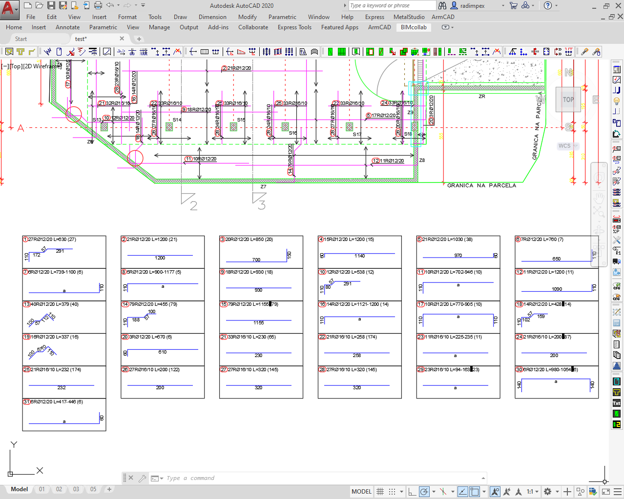
Added option of fixing one of the parameters of the bar density - the number of pieces or spacing in order to remain unchanged during the gripping of the series - has been introduced. In the case of a variable series, it is basically possible for the entered area to refer to the selected bar segment, and not, as before, exclusively to the entire bar. The placement on the drawing of a representative of a variable position with the exact geometry of one of the bars was introduced, and
placement on the drawing of the workshop drawing - the so-called "specifier with a table".
Improvements in cross-section making
When removing the cross-section, it is possible to easily manually adjust the "depth" order of the cut bars and smart memory of the order when successively removing the cross-sections from the same carrier. It is possible to place the bars in the cross section without elevation, as well as their subsequent dimensioning.
Newspapers in auxiliary tools
It is possible to archive and easily transfer all configuration files (quotation styles, regulations, report formats ...) from one user's computer to another. It is possible to automatically change the dimensioning style in the already drawn drawing. When placing a drawing frame of any format, it is possible to obtain marked bending points in accordance with several standard bending methods.
New features in the report
Added new types of reports - recapitulation of bars for each payment, recapitulation of bars according to SNIP regulations, plan for cutting bars. The display of new types of data has been added, such as the net amount of embedded nets, the total length and weight of the embedded bars, the number of pieces of whole bars, the length and weight of the bars when cutting. It is possible to generate two bar specification reports with separate content at the same time. It has been introduced that the report of each payment starts on a new page as well as that each individual report is excluded. It is possible to adjust the table view separately in the form of separate table header fonts and adjust the color of the lines in the tables. The drawing of the bar symbols in the specification has been improved by enabling different marking of arcuate, oblique and variable segments. The possibility of automatically marking out-of-date reports on the drawing has been introduced after any change that affects the specification in order to inform the user that it is necessary to regenerate the report.
Novelties in the user interface
Control and management of the program have been improved by creating more transparent dialogues and their more logical organization with the display of additional data.
Novelties in editing functions
In the database of positions of bars and meshes, new types of sorting have been introduced, as well as simultaneous sorting according to several criteria with the possibility of setting their priority, as well as the possibility of unique renumbering within several formwork. An internal separation of bar and stirrup bending styles was performed to allow easier selection of the right bending style. It is possible to lock and protect against changes by gripping on the entire formwork or on individual positions, separately for the geometry of the bar and the elevation. When creating new entities, it is possible to easily set display parameters, as well as directly call the formwork dialog and the dimension styles dialog. The possibility of warning users in the case of using geometry with too large coordinates has been introduced, as well as warnings when forming a non-plane or bar with 3D geometry as a measure of protection against errors caused by drawing on 3D surfaces.
Easy transition from ArmCAD 2005
ArmCAD 6 is fully compatible with the previous version. All drawings drawn with ArmCAD 2005 can be opened with ArmCAD 6. In addition, a reverse link is enabled, ie recording a drawing made in ArmCAD 6 in the format of ArmCAD 2005. This is easily done using the special command "Save to ArmCAD 2005 ”. An embroidered drawing like this, opened in ArmCAD 2005, will be identical to the original drawing except that it will not have all the new details and display options inherent in ArmCAD 6.
Required computer configuration
• Windows 7, 8, 10, 11
• AutoCAD 2010, 2011, 2012, 2013, 2014, 2015, 2016, 2017, 2018, 2019, 2020, 2021, 2022, 2023, 2024, 2025 or 2026 (64-bit) (LT versions of AutoCAD are not supported)
or
• BricsCAD v14, v15, v16, v17, v18, v19, v20, v21, v22, v23, v24, v25 and v26 ("Pro", "Platinum", "BIM" or "Ultimate") ("Classic" or "Lite" configurations are not supported)